Modern industrial processes demand compact, reliable, and maintenance-friendly valve solutions that improve operational safety while reducing installation complexity. In industries such as oil & gas, petrochemicals, power plants, and chemical processing, traditional multi-valve assemblies have been widely used for pressure instrumentation and process isolation systems.
However, these conventional assemblies often involve multiple fittings, connectors, and valves, increasing the risk of leakage, installation errors, and maintenance challenges. To overcome these issues, industries are increasingly shifting toward Monoflange Valves.
Monoflange valves provide a compact integrated solution that combines multiple valve functions into a single assembly, offering improved safety, reduced leak paths, and enhanced operational efficiency.
What is a Monoflange Valve?
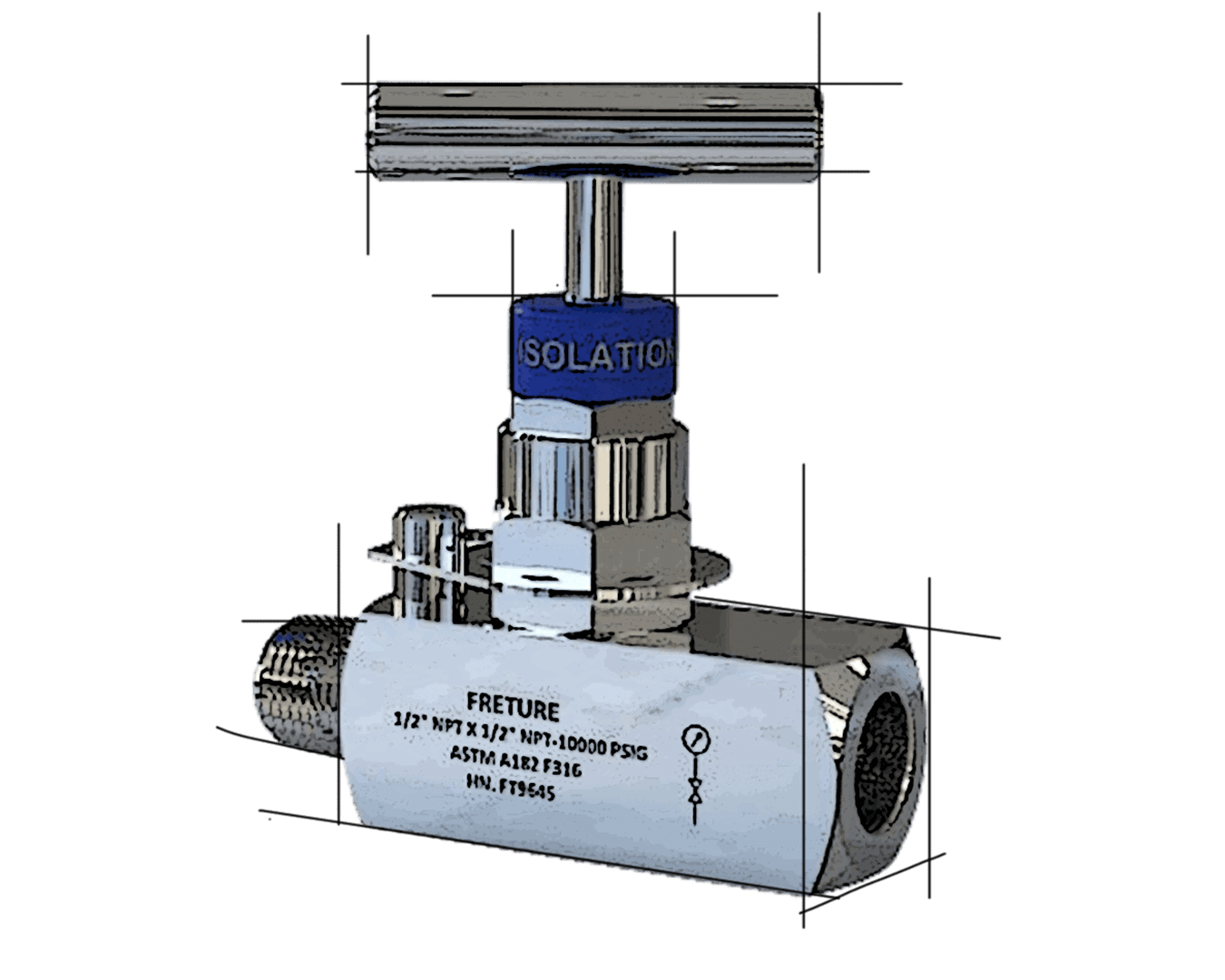
A Monoflange Valve is a compact instrumentation valve assembly designed to integrate:
- Isolation valves
- Equalizing valves
- Vent or bleed valves
into a single forged body construction.
These valves are commonly used with:
- Pressure transmitters
- Differential pressure transmitters
- Gauge pressure systems
- Process instrumentation lines
Monoflange valves simplify piping systems by eliminating the need for multiple separate valves and fittings.
Limitations of Conventional Multi-Valve Assemblies
Traditional multi-valve assemblies typically consist of:
- Multiple valves
- Pipe nipples
- Connectors
- Adapters
- Threaded joints
While functional, these assemblies introduce several operational disadvantages.
Common Challenges Include:
- Increased leakage points
- Larger installation space
- Higher maintenance requirements
- Complex assembly procedures
- Greater vibration sensitivity
- Increased weight on instrumentation systems
In critical applications, these issues can impact both safety and reliability.
Why Industries Are Switching to Monoflange Valves
1. Reduced Leak Paths
One of the biggest advantages of monoflange valves is the reduction in potential leak points.
Since the assembly is integrated into a single body:
- Fewer threaded connections are required
- Leakage risk is significantly minimized
- Process safety improves
This is especially important in hazardous fluid and gas applications.
2. Compact and Lightweight Design
Monoflange valves occupy significantly less space compared to conventional assemblies.
Benefits include:
- Easier installation
- Reduced piping congestion
- Lower structural load on transmitters
- Improved accessibility
Compact designs are highly beneficial for offshore platforms and confined industrial areas.
3. Improved Safety Performance
Safety is a major reason industries prefer monoflange valves.
The integrated forged construction helps:
- Improve pressure integrity
- Reduce vibration-related failures
- Enhance sealing reliability
- Minimize fugitive emissions
This supports safer plant operations and compliance with industrial safety standards.
4. Faster Installation
Traditional multi-valve systems require assembly of multiple individual components.
Monoflange valves simplify installation by:
- Reducing assembly time
- Minimizing alignment issues
- Lowering labor requirements
This helps industries reduce project execution time and installation costs.
5. Lower Maintenance Costs
With fewer components and connections, monoflange valves reduce:
- Inspection requirements
- Maintenance frequency
- Replacement costs
Simplified maintenance also minimizes operational downtime.
Applications of Monoflange Valves
Monoflange valves are widely used in:
- Oil & Gas Industries
- Petrochemical Plants
- Refineries
- Power Generation Facilities
- Chemical Processing Plants
- Offshore Platforms
- Instrumentation Systems
They are ideal for high-pressure and critical process applications.
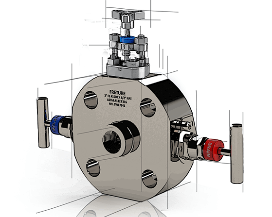
Types of Monoflange Valves
Common monoflange configurations include:
- 2-Valve Monoflange
- 3-Valve Monoflange
- 5-Valve Monoflange
Each configuration is selected based on instrumentation and process isolation requirements.
Key Features of Monoflange Valves
High Pressure Capability
Designed for demanding pressure applications.
Forged Body Construction
Provides superior mechanical strength and durability.
Compact Design
Optimizes installation space and reduces system complexity.
Leak-Tight Performance
Improves process safety and reliability.
Corrosion Resistance
Suitable for aggressive industrial environments.
Important Factors While Selecting Monoflange Valves
Industries should evaluate:
- Pressure rating
- Temperature range
- Media compatibility
- End connection type
- Material selection
- Instrumentation configuration
Common materials include:
- Stainless Steel
- Carbon Steel
- Duplex Steel
- Alloy Steel
Proper valve selection ensures long-term operational reliability.
Why Choose Freture Techno Pvt. Ltd. for Monoflange Valves?
Freture Techno Pvt. Ltd. offers precision-engineered monoflange valve solutions designed for critical industrial applications.
Their monoflange valves provide:
- Compact integrated design
- High-pressure performance
- Reliable sealing
- Corrosion resistance
- Long operational life
- Industry-standard manufacturing quality
Freture Techno focuses on delivering efficient and safe instrumentation valve solutions for modern process industries.
Conclusion
Monoflange valves are rapidly replacing conventional multi-valve assemblies due to their compact design, reduced leak paths, improved safety, and lower maintenance requirements.
As industries continue to prioritize operational efficiency and process reliability, monoflange valves have become an ideal solution for critical instrumentation and isolation applications.
Their integrated design not only enhances plant safety but also helps reduce installation complexity and long-term operational costs.
FAQ
What is a monoflange valve?
A monoflange valve is a compact integrated valve assembly used for instrumentation isolation and venting applications.
Why are monoflange valves preferred over conventional assemblies?
They reduce leak points, save installation space, improve safety, and lower maintenance costs.
Where are monoflange valves commonly used?
They are widely used in oil & gas, petrochemical, chemical, and power generation industries.
What materials are used for monoflange valves?
Common materials include stainless steel, carbon steel, duplex steel, and alloy steel.